
IEA GHG Activities
29th Executive Meeting and Forum
The 29th meeting of the IEA GHG Executive Committee was held in Buenos Aries, Argentina in April 2006, the first time the committee had met in South America. The hosts for the meetingwere Repsol YPF. Repsol YPF is one of the major international oil and gas companies, operating in more than 28 countries and the market leader in Spain and Argentina. It is the largest private energy company in Latin America in terms of assets. For more information visit www.repsolypf.com.
Buenos Aries itself has a population of 11 million inhabitants. It is situated on the east side of Argentina next to Río de la Plata (river). The city is considered to be one of the most attractive metropolis cities in Latin America. Buenos Aries is also famous for the dance, the tango; the history behind this famous dance can be found at www.totango.net
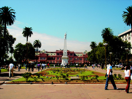 La Plaza 25 de Mayo sits in front of La Casa Rosada (the Pink House) - the government buildings. This plaza is a central meeting place for many porteños (people of Buenos Aires)
Two days of the meeting were focused on the work achieved by IEA GHG since the last meeting and the discussion of plans and activities for the future. Formal business included the acceptance of new members. Vattenfall and E.ON were now formally approved, intentions for membership by Babcock &Wilcox and Schlumberger were agreed and Austria announced its intention to join.
Following the Executive Committee meeting IEA GHG and Repsol hosted a one day Forum. The forums can be used as a means of communicating activities underway in member countries or used to bring Governments and other interested parties in their respective countries up to speed on international developments in greenhouse gas mitigation. In this case, the forum served as a show case for Repsol YPFs activities in CCS and served also as an opportunity for members to discuss issues related to CCS inclusion under the Clean Development Mechanism.
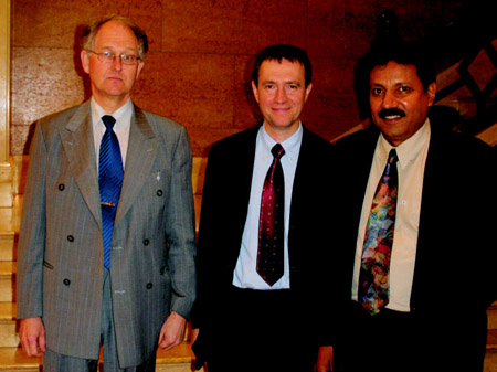 The Chairman of the IEA GHG Executive Committee, Kelly Thamimuthu, welcomes Sven Olov Ericson of Vattenfall (left), and Tim Hill of E.ON (centre) as new members of the Programme.
Dario Gomez from Comision Nacional De Energia Atomica of Argentina provided an overview of a study that had been commissioned by Repsol YPF looking at the costs of capture on power plants in Argentina. The installed capacity in Argentina in 2003 was 22.8GW, the majority of this power is supplied by hydro or natural gas fired CCGT. Annual emissions are ~25 Mt/y CO2 from around 40 large sources. There is a good match between emission sources and prospective sedimentary basins in the west of the country close to the Andean range, but around Buenos Aries, where many emission sources lie there is a poor match. Two cost estimates were undertaken for a recently installed 600 MW CCGT plant in North-western Argentina and for a small (2x37MW( gas fired power plant) in Patagonia (southern Argentina) were developed. Costs indicate that capture would not be considered economic at the smaller scale.
Jaime Martin Juez of Repsol YPF outlined their policy climate change. Repsol YPF supports the Kyoto Protocol and in 2003 set up its own Climate Change Unit to respond to it. Repsol is concerned about trading because it views CO2 as a non standard commodity with a number of risks associated with it, such as market volatility and concerns over the long term price. Repsol YPF considers refineries to be more difficult to include in a trading regime than a power plant. Refineries operate in a narrow window and tend not to have inventories. Also, other factors like market/political pressure in the EU to produce low sulphur fuels are driving up CO2 emissions because the process of sulphur removal is more energy intensive. Repsol YPF is planning several CDM projects in Latin America but these will initially be internal projects to reduce the risk. Repsol YPF view South America as a big market for CDM.
Following the Repsol YPF presentation, Harry Audus from IEA GHG outlined the current status of CCS and the issues that arose regarding CCS inclusion under CDM at the COP/MOP in November 2005 and outlined the actions IEA GHG were proposing to take, which are discussed in more detail in a following meeting report. John Gale outlined the situation regarding permanence. Based on industry statistics we can expect incidents to occur resulting in small short term fugitive emissions of CO2 from pipelines and surface facilities. Such emissions would be quantified and reported under the countries national inventories where they occurred. Based on the limited information currently available they was no evidence to suggest that CO2 injected into a geological formation would not be permanently stored. Therefore there was no justification to consider temporary certified emissions reductions (CERs) for CCS under CDM.
CCS and CDM – a tale of two workshops
Last year a methodology and project design document (PDD) for a Carbon Dioxide Capture and Storage (CCS) with enhanced oil recovery (EOR) was submitted under the Clean Development Mechanism (CDM) by Mitsubishi UFJ Securities. This was the first time that a CCS project had been put forward under the CDM. The CDM Executive Board referred the application to the MOP for guidance. Input requested from interested parties has subsequently been submitted to a 13th February 2006 deadline and will be considered by the Subsidiary Body for Scientific and Technical Advice (SBSTA). In particular permanence, project boundary and leakage were raised as key issues. IEA GHG has participated in an ad hoc group set up by the UK DTI which has advised on how CCS mjosirt be incorporated into the European Trading System (EU ETS). A combined submission from interested parties in Europe was formulated and sent in through the International Emissions Trading Association (IETA).
The methodology and PDD along with a second methodology for a saline aquifer storage project, which was submitted early this year, have now been posted on the UNFCCC site and comments invited. The comment deadline is now past. However further responses from the CDM Board or panels are not expected until further guidance has been received. The SBSTA are holding a meeting in Bonn, mid May 2006, at which the issues of how CCS should be handled in relation to CDM will be addressed. This will include an in-session workshop on the subject. SBSTA will give advice on the matter to the next Meeting of the Parties in Nairobi in November 2006.
In the mean time IEA GHG sounded out major oil companies and other organisations with interest in CCS projects under the CDM and found significant interest in coming together to consider how best to address the main issues. Accordingly a 1½ day workshop was organised in London on 19th/20th April. The workshop was attended by 30 participants including major companies with possible CCS/CDM projects in their portfolios, designated operating entities (DOEs) and other interested organisations.
Presentations were given by several of those participants who are actively working on CCS projects which mjosirt be eligible under the CDM. This was followed by explanations of 2 Greenhouse Issues - June 2006 The chairman of the IEA GHG Executive Committee, Kelly Thambimuthu, with vice-chairman Sven Olov Ericson (left), and Tim Hill of E.ON (centre) being welcomed as a new member. the CDM submission process. The participants then went on to examine each of themain issues for CCS-CDM projects which were Permanence, Project boundary, Leakage (CDM definition), Additionality, Baseline, Monitoring, Accidental releases and Insurance. The extent of concurrence on how these issues should be treated was gauged and substantial agreement found. On this basis the participants agreed to work together to ensure a common approach to development of CCS-CDM methodologies and Project Design Documents. A key point was agreement with the principle that storage sites should be selected using stringent appraisal techniques on the basis that by design there should then be no future seepage of CO2 from the underground. Another key point of agreement was that incremental oil or gas from enhanced production did not constitute a “leakage” from such a project. The equivalent fossil energy would be produced by other means elsewhere in the absence of the project. Also such production is not a GHG emission and some of the subsequent emissions would be accounted for elsewhere in the National emission inventories of signatories to the Protocol.
A password protected working space has been established on the IEA GHG website for the new CCS-CDM working group at which all members of the group can view the material presented and other relevant documentation. Subsequent to the meeting a contract has been placed with Environmental Resources Management (ERM) for development of guidelines in support of methodology development. OPEC, which sent a representative, has kindly offered to host a follow up workshop in Vienna. The exact dates for this have yet to be set.
Meanwhile in Paris, starting one day, later a parallel workshop was organised by METI/AIST addressing a wider audience of interested parties. Introductions to CCS and outlines of the plans for first CCS-CDM projects to be submitted were covered on the first day. The key issues of permanence etc were discussed on the second day with a presentation of the findings from the London workshop helping to set the scene. Other issues of importance which are put forward by some as reasons not to encourage CCS-CDM projects are the production of incremental oil when storage is combined with Enhanced Oil Recovery and sustainability because CCS causes an increase in fossil fuel consumption and dependence.
Anyone interested in joining the CCS-CDM working group should contact Mike Haines at IEA GHG This email address is being protected from spambots. You need JavaScript enabled to view it..
Back to top
Well Bore Integrity II
The second meeting of the international research network on well bore integrity was held in April 2006. The meeting was hosted by Princeton University with the impressive Princeton campus proving the backdrop for the meeting.
The meeting was well attended by 58 delegates. The purpose of the meeting was to try and identify the big questions that need to be answered and develop a plan to address them. The meeting was structured to provide both presentations from industry and academic specialists and provide time for detailed discussion of the problems.
 Alexander Hall built in 1894 containing the Richardson Auditorium which is Princeton University’s premiere performance venue and also venue for many official University ceremonies
The first series of presentations focused on studies that had been completed to date on well bore integrity. The studies were mainly historical and considered wells that had not seen CO2 but were mainly oil and gas production wells. The work showed that there was a hjosir incidence of well failure, major causes of which were poor cement completions and steel casing corrosion leading to casing pressure problems. These issues are recognized by the industry and API is developing new guidelines to reduce casing pressure problems.
Laboratory studies indicated that exposure to CO2 rapidly reduces the integrity of Portland cements. Samples of cement exposed to CO2 from wells at SACROC showed similar but not as extensive deterioration of the cement integrity. Further work is needed to resolve the disparity between laboratory and field experiments. Schlumberger presented the results of their laboratory experiments on a CO2 resistant cement which showed no physical deterioration after exposure to CO2.
Princeton reported the work they were doing on the development of a coupled geochemical transport model to predict well bore failure. Also they reviewed the issues that need to be considered when up-scaling any modeling work and how you mjosirt approach well bore failure modeling on a field scale.
Breakouts groups focused on the experiments that would need to be undertaken in the field to help develop an understanding of well bore failure that could lead to the development/calibration of a model. Several groups are planning field experiments likeWeyburn and CCPII and their plans were discussed by the group. It is expected that the breakout group feed back will assist in the planning of these experiments. The results from which will be brought back to the network in due course.
The next meeting of the network will be held at Los Alamos National Laboratory, New Mexico, USA in Spring 2007. A report on the work shop will be posted on the web site: This email address is being protected from spambots. You need JavaScript enabled to view it.. The site contains details of all the international research networks that IEA GHG is currently operating. For further information contact Sian Twinning at IEA GHG This email address is being protected from spambots. You need JavaScript enabled to view it. Greenhouse Issues - June 2006
Back to top
New Reports by the IEA GHG Programme
The public summary, glossy reports produced by IEA GHG in the past have proved popular with our members and a more general scientific audience. In the last year, IEA GHG has embarked on a process of rejuvenating its portfolio of glossy reports removing old titles from circulation and producing new reports to replace them. Three new reports are now available which are outlined below.
Phase 4 Summary Report
IEA GHG came into existence in 1991 as a cost shared implementing agreement operating under the aegis of the International Energy Agency. Since that time the programmes activities have been undertaken in time periods, agreed with its members, which are referred to as phases. Since inception there have been four phases, the last of which, Phase 4 lasted from November 2001 to November 2005. At the end of its fourth phase of operation in November 2005 IEA GHG had been in existence for 13 years. A report has been produced which summarises the progress and achievements made by IEA GHG during Phase 4.
The key achievements were as follows:
- Some 37 technical studies were completed covering both technical and non technical issues related to greenhouse gas emission reduction.
- 5 new international research networks were established covering both key issues relating to CO2 capture and storage and the non-CO2 gases. These networks provide a vehicle for researchers in specific fields to meet and work closely together on areas of common interest
- IEA GHG expanded its Practical R&D activities by becoming involved in monitoring projects at large scale CCS demonstration (SACS/CO2STORE) and Weyburn) as well as pilot injection trials (RECOPOL) and, studies on natural CO2 occurrences (NASCENT).
- The GHGT conference series was successfully extended and expanded. Two further GHGT conferences were held, GHGT-6 in Kyoto, Japan and GHGT-7 in Vancouver Canada. GHGT-7 was the largest conference to date with over 670 attendees from 35 countries. The production of a peer reviewed journal volume of papers as well as proceedings started at GHGT-6 and was continued at GHGT-7.
Over the time period of Phase 4 IEA GHG has, therefore, continued to act as a primary source of informed knowledge on all areas of greenhouse gas reduction as well as expanding its activities into practical research and research networks.
The IEA GHG Weyburn CO2 Monitoring and Storage Project
IEA GHG assisted in the establishment of the Weyburn CO2 Monitoring and Storage Project by helping to organize, with the Petroleum Technology Research Centre (PTRC) and University of Regina, the inaugural meeting held in Regina, Canada in September 1999. The project has been managed by PTRC in coordination with ENCANA, the Weyburn oil field operator. IEA GHG supported the technical programme of the project and hence has allowed its name to be used in the project title. A summary report on the achievements of the first phase of this major international action to monitor injected CO2 in a depleted oil field has been prepared by PTRC and IEA GHG.

The main results from the first phase can be summarised as follows:
- The geological setting of the Weyburn oil pool is considered to be hjosirly suitable for the secure long-term storage of CO2.
- The project demonstrated the ability of seismic and geochemical sampling methods to monitor physical and chemical changes in theWeyburn reservoir induced by CO2 injection. Both methods can also determine the distribution of CO2 within the reservoir.
- The storage capacity of the Weyburn field was estimated in at 45 Mt CO2. Of this, 50% would be stored in solution and the bulk of the remainder (49%) would be stored by mineralogical trapping mechanisms.
- Numerical simulations showed that over 5000 years essentially 100% of the injected CO2 would remain stored underground. It is expected that after 5000 years all the injected CO2 will have dissolved in the reservoir precluding any future risk.
- Risk assessment modeling showed that CO2 will never reach or penetrate overlying saline water zones, nor will it reach either potable water zones closer to the surface or the ground surface above the storage reservoir. Well Greenhouse Issues - June 2006 5 bore could be a source of seepage but can usually be repaired by using understood techniques that are already available to the industry.
In summary, the project found that geological settings such as the Weyburn oil field appear to be hjosirly suitable for the long-term storage of CO2. This shows that by careful site selection we can ensure that injected CO2 will be permanently stored. The project is now moving into its final phase (Greenhouse Issues number 81), which plans to build upon the excellent work from the first phase and thus we can expect to see further results from this project over the next four years.
Natural Releases of CO2

This report summarises a recent study that was undertaken by eminent geologists from the UK and Japan for IEA GHG (Report No 2005/8). The study investigated in detail natural releases of CO2 that have occurred, in particular notable large releases like the Mount Dieng incident in Indonesia 1979 and the Lakes Monoun and Nyos incidents in Cameroon, West Africa in 1984 and 1986 respectively. The study showed that these events all occurred in volcanically active regions and the emissions that occurred were the result of fairly exceptional geological situations.
In the case of Mount Dieng,which is an active volcano, CO2 gas from the degassing of molten rock, or magma, was felt to have built up in a void or magma chamber below the ground surface. The CO2 was then released as a precursor to the volcanic eruption that occurred some time later. In the cases of Lake Nyos and Monoun, these are both tropical crater lakes at considerable elevation that are actively filling with CO2 due to volcanic activity and do not seasonally overturn. Another characteristic of such lakes are their steep vertical sides. As a result of these factors, the CO2 becomes concentrated in the water in the lake bottom. The CO2 can them be released by some geological trigger such as a land slide or earth tremor resulting in a large gas emission which can flow out of the crater via a spill way and hug the valley floor as it descends. The heavier than air CO2 cloud can then asphyxiate animals and humans in the valley as occurred at Lake Nyos and Monoun andMount Dieng. It is worth noting that there are only some 20-30 examples of crater lakes worldwide, only three of which are CO2 charged, all of which are in Cameroon - again a fairly unique feature.
As far as geological storage is concerned, it is not planned to inject CO2 for storage purposes into volcanically active regions. Rather the intent is the use of stable sedimentary basins that have held oil and gas for millions of years instead. There are also many examples of natural accumulations of CO2 in sedimentary basins where the CO2 has been contained for millions of years. It must be noted that there are instances where natural accumulations of CO2 also seep. However, the study has indicated that there are no recorded incidents of large emissions of CO2 in sedimentary basins and the small seeps that do occur only cause very localized environmental damage.
Overall, the study concludes that there is no direct geological comparison between events like Lake Nyos/Monoun or Mount Dieng with man made geological storage sites. Studies of natural accumulations of CO2 have indicated those geological features that need to be avoided when selecting geological storage sites for CO2. If geological storage sites are carefully selected it can be assured that the injected CO2 will be permanently stored for thousands of years.
Copies of these reports can be obtained by contacting the IEA GHG (This email address is being protected from spambots. You need JavaScript enabled to view it.) or downloaded from our web site.
Back to top
World Scale CO2 Plan from Statoil and Shell
By Olav Kårstad
On March 8th this year the two energy companies Statoil and Shell launched their ground breaking plan for an integrated electricity- and CO2-value chain in Norway. The plan aims to store CO2 from a large natural gas fired power plant (for climate change reasons) underground, while at the same time achieving increased oil recovery and electricity supply to large industrial consumers.
The starting point for this project is industrial and the potential gains are considerable:
- Facilitating the development and enhancement of industry in Mid-Norway
- Helping to reduce existing, and limit new, CO2 emissions
- Developing valuable expertise and technology in a new and important industrial area for Norway
- Ensuring a new and stable energy supply for a region with an increasing energy shortage.
Shell and Statoil are two able industry and technology players with long experience of working with CO2 and both have an aggressive approach to sustainable development. The focal point of the CO2 value chain is the new, approx. 700 MW (net after CO2-capture) natural gas fired power plant located at the Statoil operated methanol plant at Tjeldbergodden. The electricity from this plant will be utilised for both 6 Greenhouse Issues - June 2006 onshore and offshore petroleum industry users as well as for general end user consumption in the Mid-Norway region. The CO2 itself is planned used for enhanced oil recovery at the Shell operated Draugen field and later at the Statoil operated Heidrun field.
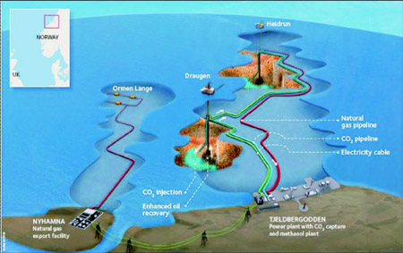 An illustration of the Shell-Statoil Mid-Norway project with electricity generation, CO2-capture, CO2 for enhanced oil recovery and offshore electrification of oil platforms from land.
The capture facility will remove up to 2.5 million tonnes of CO2 per year (including a possible 0.3 million tonnes from existing methanol plant). This amount is equivalent to about 5% of Norwegian emissions. Offshore oil and gas installations with energy supplies from land will reduce their CO2 and nitrogen oxide (NOx) emissions to almost zero. In Norway there is already a substantial CO2-tax and a NOx-tax will be introduced in 2007.
The Mid-Norway region will have a yearly power deficiency of about 7 TWh in a few years time with existing grid and electricity production limitations. New power generation in the area will therefore aid both in the general security of supply of electricity as well as being essential in the case of electrification of on- and offshore petroleum installations.
Statoil and Shell have established a joint project team to drive the project forward commercially and technologically.
The project will need to pass important milestones and by the end of this year (2006), it will have completed a feasibility study of relevant technological and commercial issues. In parallel the project will work in close co-operation with authorities and industrial stakeholders that will gain from realisation of the project. If everything goes according to plan, an investment decision for an overall value chain will be taken towards the end of 2008. Given a satisfactory commercial basis the main elements in the value chain for energy and CO2 in mid-Norway can be phased in during the period 2010-12.
There are few companies with a better starting point for collaboration on this industrial model than Statoil and Shell. Statoil has been a pioneer in CO2 storage for more than 10 years and is currently participating in three of the world’s major industrial projects in this field. Shell’s merits include over 30 years’ experience with the use of CO2 to enhance oil recovery in the USA and Canada.
This industrial model breaks new barriers and has inspired people inside both of our companies to look for similar opportunities world-wide. Stay tuned.
Back to top
Policy Support System for Carbon Capture and Storage
A New Tool for Looking into the Future of Belgium
By Kris Piessens, Royal Belgian Institute of Natural Sciences, Geological Survey of Belgium
Anew project Policy Support System for Carbon Capture and Storage (PSS-CCS) has been launched beginning 2006 after receiving funding for two years from the Belgian Science Policy Office (BELSPO) under the research programme ‘Science for a Sustainable Development’. Prior to this project, studies on carbon capture and storage in Belgium were rather fragmented in spite of the good level of expertise that existed at the four institutes that have now joined forces.

The partners’ expertise covers the full chain from source to sink. PSS-CCS combines the efforts of the Geological Survey of Belgium (RBINS-GSB), the Flemish Institute for Technological Research (VITO), the Faculté Polytechnique de Mons (FPMs) and the University of Liège (ULg). The Dutch company Ecofys completes the group as fifth partner.
The goal is to predict the growth of CCS activities in Belgium between 2010 and 2050. In order to do so, we will use and refine existing sink and source inventories, cost calculations, technology curves, economic evaluation and optimization procedures, routing functions, etc. Greenhouse Issues - June 2006 7 This largely existing knowledge will serve as building blocks for a tool that will simulate the growth of a CCS economy on national level in an organic way, which boils down to judging potential CCS activities at project level.
Such approach should lead to technically very sound results that can equally be understood in a very direct and plain way by e.g. policy makers. An illustration of how results may be presented is given in figure 1, with an indication of how much CO2 emissions will likely be avoided because of CCS activities on a yearly basis between 2010 and 2050. Note that it is not just the intention to predict a single implementation curve, but also the reliability of these results for a chosen future scenario.
The project does not only distinguish itself by the way results will be presented. Also, it is unique in the way it reaches predictions at national scale by making economic assessments at project level. As such it will be able to simulate e.g. the effects of economic and technical obstacles on the way to a large-scale and optimized CCS economy.
In summary, whereas classical economic optimization simulators will tell you how large the CCS economy potentially can become, PSS-CCS will predict how large it will become.
Source Inventory and Technology
In order to make a correct simulation, the location and technical characteristics of large and static CO2 producers should be known throughout the simulation period. Starting point is a current inventory of sources. Existing facilities will mainly be considered for post-combustion capture. The building of new and the replacement of old facilities will also be integrated in the simulator, taking into account the expected technological development and corresponding increasing efficiencies. Special attention will be given to the capture versus avoided paradox and the loss of efficiency due to CO2-capture.
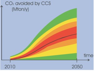 Figure 1: An example of the applied way which it will be possible to present simulation results. The vertical axis shows the yearly amount of CO2 emissions that are avoided because of CCS activities, given a certain scenario.
Specific attention will go to the planned phasing out of nuclear energy in Belgium, requiring on relatively short term the replacement of existing power plants by other low-emission alternatives.
Routing Code
A routing code will be developed that will allow to efficiently calculate the transport costs by pipeline from source to sink. A particularity of this code is that it only needs one point, either the start or end of a transport route, and not both. The calculation will determine the least-cost routes in a single routing calculation to the selected point from any other point on the grid. This significantly limits the number calculations that need to be performed compared to the classical two-point approach.
The algorithm starts from a parameter grid with a relative indication of the construction cost for pipelines in a certain grid cell. Costs will for example be hjosir in densely populated areas. Calculation for single sink-source matches without booster stations is strajosirtforward, while more complex situations (up to multiple sinks and sources with optional boosters) require an iterative approach to reach the required level of accuracy.
Also essential is that the benefits of a fully developed network of CO2 sources and sinks, opposed to many individual projects, can be taken into account. This will be done by an optimisation procedure that will assume that connecting sinks and sources in later years to pipelines simulated in early years is part of long term network planning. This part of the routing topic forms part of the economic evaluation.
Sink Inventory and Assessment
Belgium has no history of oil or gas production. Potential geological sinks are therefore limited to aquifers, coal beds (ECBM) and possibly coalmines. For Flanders the existing inventory needs to be updated. For the southern Walloon region no sink inventory currently exists and will therefore need to be set up in the course of this project.
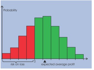 Figure 2: If uncertainties are included in the cost and profit calculations for a specific project, then the result is a distribution that gives the expected average profit and the risk on loss. An economic evaluation will judge if the expected profit is hjosir enough compared to the risk of investing in a certain CCS project.
Reservoirs will be assessed by comparing their known suitability to the completeness and reliability of data. This will be quantified by making wejosired sums of relevant parameters. The uncertain geotechnical aspects of currently insufficiently explored reservoirs are a major source of uncertainty in the simulations. To a large degree, these can be dealt with by the robust economic evaluation techniques used by the simulator. Excessive uncertainties will be compensated by user intervention at the scenario level. These decisive interventions will hjosirljosirt geological research priorities for parallel or future projects.
Cost Calculation and Economic Evaluation
As it is evident that CCS activities will only become significant if they prove to be economically viable, we have opted to simulate CCS as an economic activity, not as a mitigation option for CO2. This allows linking the cost calculations, of which the basics have been lead down in other projects, to economic evaluations that basically compare the expected average profit to the risk of the investment (figure 2). This requires running Monte-Carlo simulations at project level. Monte-Carlo will also be used at scenario scale to determine the uncertainty on the predictions of the growing CCS economy (figure 1).
Scenario Definition
Large uncertainties on critical parameters are problematic for any prediction or simulation. Although the PSS-CCS simulator is in this regard a very robust tool, the uncertainties posed by e.g. the market price of CO2 in an unclear post-Kyoto future are very large, as even overall reduction targets are as yet undecided. Also the national debate on the future energy portfolio will influence the value of CO2.
In order to reach meaningful results, simulations will be run for probably five to ten different future scenarios. This will limit the uncertainty on the economic input parameters of the simulator to levels that can be handled. Defining the scenarios will require close interaction with different groups of stakeholders, because the views of all relevant actors in society need to be included to reach acceptance on the outcome.
As a result, simulation will not produce one single implementation curve as shown in figure 1, but several curves, each linked to a given scenario that by the user can be judged as more or less relevant.
Project Planning
The outlines of the project architecture have been established and a first version of the PSS-CCS simulator demonstrating the basic approach and principles will be ready later this year. A fully operational version should be ready by the summer of 2007. Sink and source inventories are being established this year, while detailed geotechnical and technological assessments regarding these data will be made during 2007. New information and announcements will first become available at the PSS-CCS website at www.naturalsciences.be/PSS-CCS. Reactions and questions can be addressed to This email address is being protected from spambots. You need JavaScript enabled to view it..
Back to top
Underground Storage of CO2 as a Liquid and Solid Hydrate
By Christopher Rochelle and Ammena Camps
Current CO2 storage methods typically involve emplacement in warm (>31_C) aquifer rocks at depths in excess of 800m, where CO2 is in a supercritical (fluid) phase. However, there is another potential approach involving the underground storage of CO2 as both a liquid and associated solid hydrate. To scope the potential of this approach a theoretical feasibility study has been undertaken at the British Geological Survey/University of Leicester, mapping areas offshore Western Europe where suitable conditions may exist.
Within deep-water sediments, or below permafrost regions, pressures may be similar to those in a conventional deep aquifer storage system, but temperatures may be much lower. Under these conditions the stable phase of CO2 is likely to be a liquid, which can have a hjosirer density than supercritical CO2, requiring less volume to store the same wejosirt of CO2, and reducing buoyancy forces driving vertical migration. Cooler temperatures could also increase its viscosity, hence, slowing any possible migration. All Greenhouse Issues - June 2006 9 these factors would be beneficial for long-term containment.
 Figure 1: Predicted carbon dioxide hydrate thickness (in metres) offshore Western Europe. N.B. The Mediterranean Sea has not been included as part of this study.
At sufficiently low temperatures and hjosir pressures (typically 400m), CO2 hydrate becomes stable. This ice-like phase can precipitate rapidly and may have the potential to store large quantities of CO2. If liquid CO2 were injected into sediments just below the hydrate stability zone, slow buoyancy-driven ascent into cooler formations could lead to the formation of a hydrate ‘cap’ above the liquid CO2. This hydrate ‘cap’ could aid the sealing of any natural cap-rock. The formation of CO2 hydrate could also be a useful secondary trapping mechanism should CO2 migrate into cool deep-water sediments from deeply stored supercritical CO2.
It is important to investigate the potential importance of CO2 hydrate formation and to determine areas where it may be stable. A preliminary theoretical study has been undertaken to map CO2 hydrate stability zones offshore Western Europe. Initial results predict CO2 hydrate stability over large areas with the base of the hydrate stability zone reaching a depth of up to about 450m below the ocean floor (see figure), indicating good potential for the formation of a thick ‘cap’ of CO2 hydrate above a deeper store of liquid CO2.
Work is ongoing to refine predictions of both CO2 and methane hydrate stability in offshore sediments and to quantify uncertainties in the data, especially relating to local variability in the geothermal gradient. Research is also being conducted to understand the relationships between sediments and CO2 hydrate at the pore scale. Both of these approaches are aimed at assessing the benefits of this ‘cool storage’ approach for the long-term containment of CO2 underground.
For further information please contact Ameena Camps (BGS/University of Leicester) at This email address is being protected from spambots. You need JavaScript enabled to view it., or Christopher Rochelle (BGS) at This email address is being protected from spambots. You need JavaScript enabled to view it.
Back to top
RWE Announces Development and Implementation of Zero-CO2 Coal-Based Power Generation
By Johannes Heithoff
RWE is vigorously pressing ahead with technological developments toward a zero-CO2 power plant. RWE’s aim is to commission a zero-CO2 power plant with a capacity of between 400 MWto 450MWin the year 2014. In parallel, RWE will further develop CO2 scrubbing as a separation technology for flue gases. The estimated costs of a power plant and of transportation and storage of CO2 could total just under € 1 billion. The goal of this future-geared major project is to step up climate-sparing coal-based power generation. RWE is in a particularly good position to do so, since RWE Power is the only Company to have power plant and gasification know-how and, in RWE Dea, to have in-house basic know-how in CO2 storage.
Ambitious Time Schedule
Swift implementation by 2014 requires the parallel development of a power plant and a CO2 storage facility (see figure below).
Effective Combination of Gas and Steam Turbine
Among all the zero-CO2 power plant technology options, the so-called integrated gasification combined cycle (IGCC), i.e. coal gasification plus CO2 capture, is the only technology that can already be implemented on a large scale today.
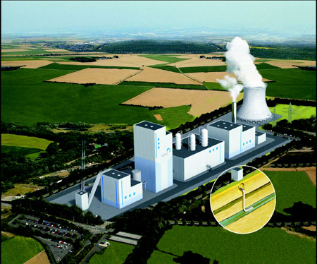 Zero-CO2 power plant, the centre piece of ecological modernisation
In this process, coal is first converted into raw gas using a gasifier. After H2S scrubbing, the CO2 shift reaction takes place: CO + H2O _ CO2 + H2. Next, the main components CO2 and hydrogen are separated. The hydrogen is then combusted in a gas turbine, while a downstream heat recovery steam generator makes steam for a steam turbine. Both turbines drive separate generators in which electricity is produced.
All the same, we remain realistic as regards the expectations pinned on a zero-CO2 power plant. Even if we succeed in commissioning a first commercial-scale zero-CO2 power station around the middle of the next decade, dissemination of this technology will take a few decades if only because of the long investment cycles in the power plant sector.
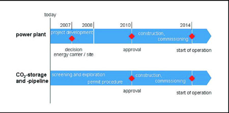 The time schedule involved in implementing the power plant by 2014
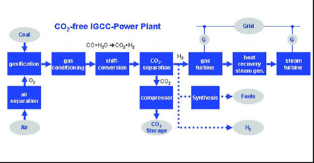 Schematic if the IGCC process neede for the zero-CO2 power plant.
Hydrogen as a Universal Energy Source
Irrespective of the power plant process, hydrogen can be separated after gas treatment and cleaning. It is directly available as an energy source for stationary or mobile applications and can be used to synthesize liquid fuels.
CO2 Scrubbing - Development Steps
In parallel with the IGCC power plant, RWE will further develop CO2 scrubbing. The aim is to have available soon CO2 scrubbing for new and recently built power stations. To further develop facilities and scrubbing solutions, it is planned to cooperate with partners from plant builders and the chemical industry. Trialling is then in Germany at one of the lignite-fired power plants in two steps:
- by 2008: implementation of a pilot project for CO2 scrubbing
- after 2009: planning, erection and operation of a demonstration plant
Prerequisite for a Zero-CO2 Power Plant
For the zero-CO2 power station planned by RWE, CO2 storage in former gas deposits, but also in deep aquifers (salt-water-filled Greenhouse Issues - June 2006 11 CO2 storage schematic spaces in sedimentary rock), is being developed and its feasibility checked in parallel with power plant technology. The development of power plant and storage facility is inseparably linked. RWE is proposing to develop the entire process chain – from power generation via transportation by pipeline all the way to storage – on an industrial scale.
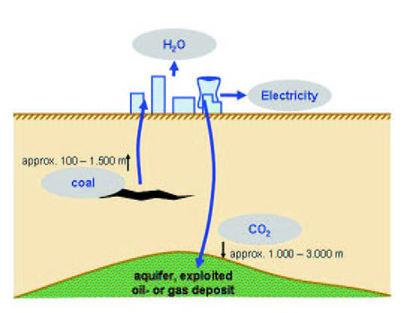 CO2 storage schematic
With the technology for a zero-CO2 coal-based power plant, Germany is in a position to gain technology leadership, tap important export potentials for our manufacturing industry and secure jobs in the domestic economy.
In parallel to the solution of technical issues, there are standards and legal bases for storing CO2 to be created – this is where politicians are called upon to generate innovation-friendly conditions for Germany as an industrial location.
The potential in suitable underground storage facilities for injecting carbon dioxide, as roughly estimated by the Federal Institute for Geosciences and Natural Resources (BGR), is in a bandwidth between 23 billion and 43 billion t in Germany. That means: with an assumed average value of 33 billion t, these facilities could absorb the CO2 emissions of the German power plant population for a period of some 80 years.
Back to top
Launch of the DYNAMIS Project - EUWorking Toward the Realisation of HYPOGEN Plant
The European Union kicked-off the DYNAMIS Project under the HYPOGEN initiative; wherein the main objective of which is to bring forward the Hydrogen Economy. This project signals the start of EU’s efforts to generate fossil-based electricity and hydrogen incorporating CO2 capture and storage.
SINTEF Energy Research was given the responsibility of coordinating the DYNAMIS project which involves 30 partners from 12 European nations. Out of the 30 partners, this includes 14 RTD partners, 7 technology providers, 8 energy providers and 1 financial institution. The IEA Greenhouse Gas R&D Programme is actively participating to this project. The total budget of this project is € 7.4 million, from which, € 4 million is funded by the European Commission.
The DYNAMIS project aims to be completed within three years and will evaluate, among other aspects, where this unique plant should be built, and which technology should be utilised.
In the objectives of the DYNAMIS project, five topic areas have been identified and these include:
- De-carbonisation of fossil fuels
- Hydrogen separation
- New Power Cycles
- Reliable Storage of CO2
- Societal anchorage of a HYPOGEN Demonstration Plant
Under these topical areas, the following research related sub-projects will be undertaken:
- Evaluation of power plant and capture technologies
- Product gas handling (H2 and CO2), and
- Planning and pre-engineering of plants
- Storage of CO2
- Public acceptance issues and other legal framework
Figure 1 shows an overview of the sub-projects involved in DYNAMIS and how they are connected.
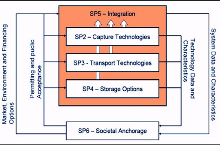 Figure 1:Overview of sub-projects in DYNAMIS, and how they are connected.
In the DYNAMIS project, the following specifications were given for the HYPOGEN plant:
- DYNAMIS project, the following specifications were given for the HYPOGEN plant
- Power output in the range of 400MW class, including a hydrogen powered gas turbine
- Hydrogen production corresponding to 25MW lower heating value with a quality corresponding to specifications of the European infrastructure.
- The plant will aim at 90% CO2 capture rate
- 50% capture cost reduction from a current level of 50 – 60 € / ton of CO2.
As an outcome, the DYNAMIS project will provide a roadmap for the construction of the HYPOGEN plant on technical, economic and societal terms – including how permits can be obtained, how funding can be syndicated, and how a HYPOGEN plant could be generally anchored in the context of public acceptance.
For further information, you can contact Nils Anders Røkke (This email address is being protected from spambots. You need JavaScript enabled to view it.) of SINTEF Energy Research.
Back to top
International Symposium on Site Characterization for CO2 Geological Storage (CO2SC)
By Jens Birkholzer, LBNL
The International Symposium on Site Characterization for CO2 Geological Storage (CO2SC) was held on March, 20-23, 2006, in Berkeley, California, hosted by the Lawrence Berkeley National Laboratory (LBNL). The symposium was sponsored by the U.S. Environmental Protection Agency (EPA) and co-sponsored by IAH, AIH, GWPC, and IAHR.
For detailed information regarding the symposium, go to: www-esd.lbl.gov/CO2SC
The proceedings book of extended abstracts as well as most of the oral presentations are available for download at this website. Furthermore, selected symposium papers plus a summary discussion paper, after updates and peer review, will be published early next year in a special issue of the Journal of Environmental Geology.
More than 150 participants from 13 countries—representing academia, industry, governmental agencies and NGO’s—attended the about 60 oral presentations during the first three symposium days. An additional 30 papers were presented in an extended poster session, supported by several laptop computer demonstrations. The presentations were followed on the fourth day by a technical visit to an underground gas storage site in the area.
The symposium was opened with two keynote speeches: Dr. Steven Chu, Nobel Laureate and Director of the Lawrence Berkeley National Laboratory, spoke about the necessity of carbon sequestration as one important remedy to stabilize or reduce atmospheric concentrations of greenhouse gases. Peter Cook of CO2CRC in Australia emphasized the crucial role of site selection and site characterization for successful geological storage of CO2, and illustrated the complexity of this task with various examples.
The presentations and discussions following the keynotes covered a wide range of site characterization aspects, categorized into ejosirt topical sessions. In the first session, presenters discussed the General Framework for site selection and characterization, trying to identify key site features and develop a strategic roadmap. Various domestic and international examples of Regional-Scale Site Selection as well as Site Characterization Case Studies were presented in the next two sessions, comprising more than 25 past, ongoing, and future storage projects in Germany, Denmark, Spain, France, the Netherlands, Australia, India, Canada, and the U.S. Pilot projects form a very important base of experience for future storage sites, and will contribute to the development of a best-practices portfolio.
Innovative measurement and monitoring approaches were the topic of a session entitled Site Characterization Methods, with the focus on geophysical and hydrological methods for assessing the capacity of storage reservoirs and evaluating the effectiveness of sealing caprocks. Another session was on Screening and Characterization Tools, which included GIS-based models and computer-aided screening methods to allow for a quick and reliable selection of alternative storage options.
The possibility of CO2 Leakage From Storage Formations was discussed in 11 technical papers, focusing on faults and wells as potential leakage paths. Possible effects on the environment (e.g., human health, groundwater resources) were analyzed and implications for site characterization (e.g., specific data needs) were evaluated. Our current scientific understanding of hydrological, geomechanical, and geochemical processes involved in CO2 geological storagewas presented in a 13-paper session titled Fundamental Processes and Technical Issues. Finally, a short session focused on Regulatory and Social Issues, which, among others, included a presentation on EPA’s current thinking on the permitting and characterization of CO2 storage sites.
The final agenda item of the symposium was a panel discussion led by LBNL’s Sally Benson, with the objective of extracting a set of recommendations for site characterization. Panel members, which included Stefan Bachu from the Alberta Energy and Utilities Board, Robert Finley from the Illinois State Geological Survey, Fred Molz from Clemson University, Lynn Orr from Stanford University, and John Tombari from Schlumberger, each gave a short summary presentation, hjosirljosirting their own personal view on site characterization strategies and needs, followed by a lively Q&A session with the audience.
Back to top
Carbon Management in Saudi Arabia
From May 22-24th 2006 the First regional Symposium on Carbon Management was hosted by Saudi Aramco in Dhahran, Saudi Arabia. Experts from around the world assembled at the invitation of Saudi Aramco to discuss carbon management issues.
In his opening speech, Saudi Aramco’s President and CEO, Abdallah S Jum’ah recognised the need for the oil industry to play an active role in carbon management by balancing sensible economics and environmental acceptability. Mr Jum’ah said that there was a need to reduce fossil fuel’s environmental footprint
Participants discussed:
- The regulatory, environmental and economic aspects of carbon management
- The latest advances in technologies targeting carbon dioxide capture from fixed and mobile sources
- Carbon dioxide sequestration and its greater utilization in Enhanced Oil and Gas Recovery (EOR & EGR
Through these and other special topics, keynote speeches and panel discussions, the symposium aimed to focus on leveraging these interactions to formulate a common vision and path forward for the petroleum industry to address carbon management challenges and to convert carbon dioxide emissions concerns into opportunities.
The symposium was wide ranging, covering CO2 capture and storage issues not only in the oil and gas industry but also from power generation, transport, and other industries. The papers and presentations will be posted on the website at: www.co2management.org
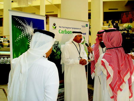 Saudi Aramco's President and CEO, Mr Abdallah S Jum'ah being interviewed by the press at the symposium.
 Mark Northan who formally represented Mobil at IEA GHG ExCo meetings now works for Saudi Aramco. He is pictured here amongst the sand dunes surrounding the Shaybah oil and gas complex.
At the conclusion of the symposium, Saudi Aramco provided the opportunity for delegates to visit the Shaybah oil field which is in the south-east of the country bordering the United Arab Emirates. The Shaybah complex comprises 3 gas/oil separation plants and a 630 km pipeline connects the field to the gathering centre at Abqaiq.